

Trumouse Pro: System Architecture
The system comprises the Compute Unit, the Reader Array (RFID floor platform), the Industrial Camera, the environmental sensor and the Infrared Lights. The Reader Array and the environmental sensor are connected to the same switch by network cable and sit on the same local network as the Compute Unit, which uses the router supplied by Murinova; the Industrial Camera connects to the Compute Unit by USB 3.0. The Compute Unit has its own power supply; the other parts are powered from DC supplies. All communication between subsystems is wired. Apart from the 134.2 kHz LF RFID reader function, the system has no other wireless functions; see Radio Characteristics.
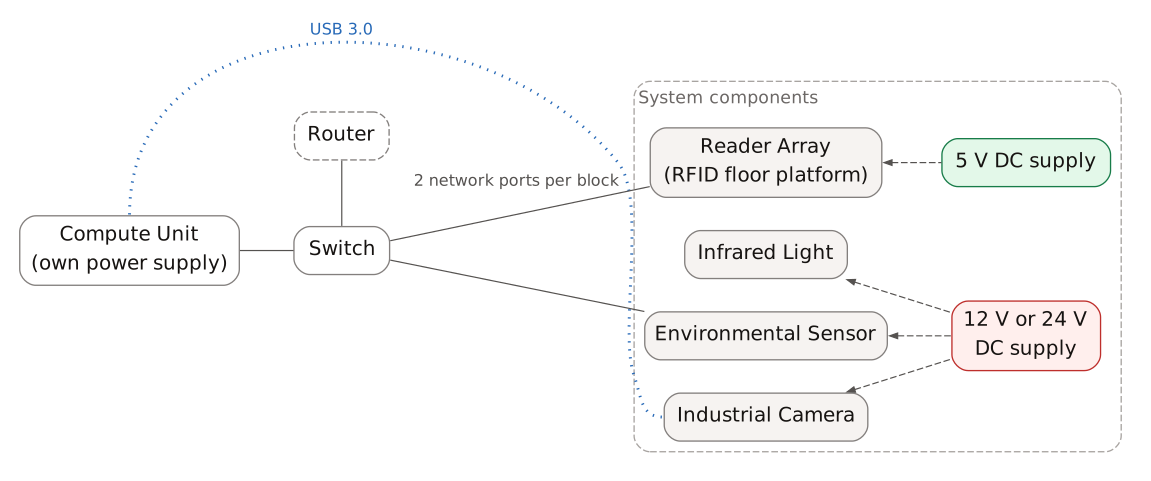
Figure: System topology. Solid lines indicate network cable connections; dashed lines indicate DC power; the dotted line indicates the USB 3.0 connection (Industrial Camera). The dashed outline marks the router.
RFID Reader Array
Section titled “RFID Reader Array”The floor platform (RFID floor platform) contains reader coils arranged at equal spacing, each coil forming one reading position. The coils completely cover the activity area and read the Passive Transponder Tags implanted in the animals. The centre-to-centre spacing between adjacent coils is 100 mm. The reading positions are divided into blocks. Each block has 2 network ports and 2 DC power inputs. The network ports connect to the switch by network cable; the DC power inputs connect to one DC supply through a 1-to-2 DC splitter cable.
See Figure “Reader Array layout showing the reading positions, network ports and network cables” for the layout.
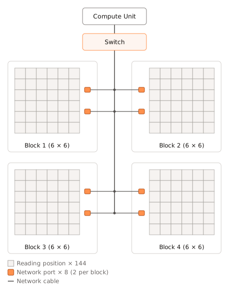
Figure: Reader Array layout showing the reading positions, network ports and network cables.
Table: Reader Array specifications
| Parameter | Value |
|---|---|
| Activity area | 1200 mm × 1200 mm |
| Blocks | 2 × 2 (4 blocks total) |
| Reading positions per block | 6 × 6 |
| Total reading positions | 144 |
| Total network ports | 8 |
Figure “Top view of the Reader Array with the cover plate removed” and Figure “One block” show the Reader Array itself, and Figure “Section through the Reader Array, with the cut faces in orange” shows its structure.
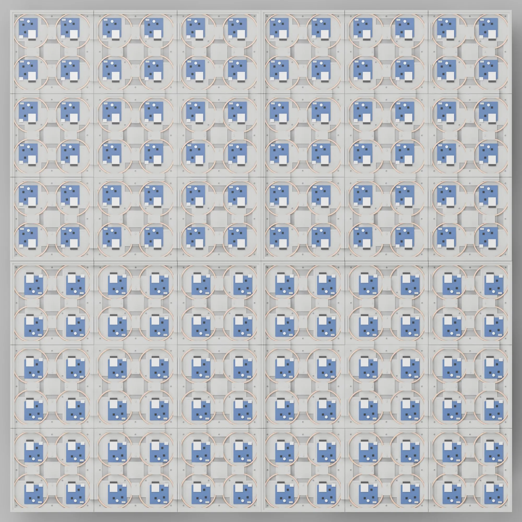
Figure: Top view of the Reader Array with the cover plate removed. Blocks: 2 × 2 (4 blocks total); 144 coils at equal spacing, covering the activity area
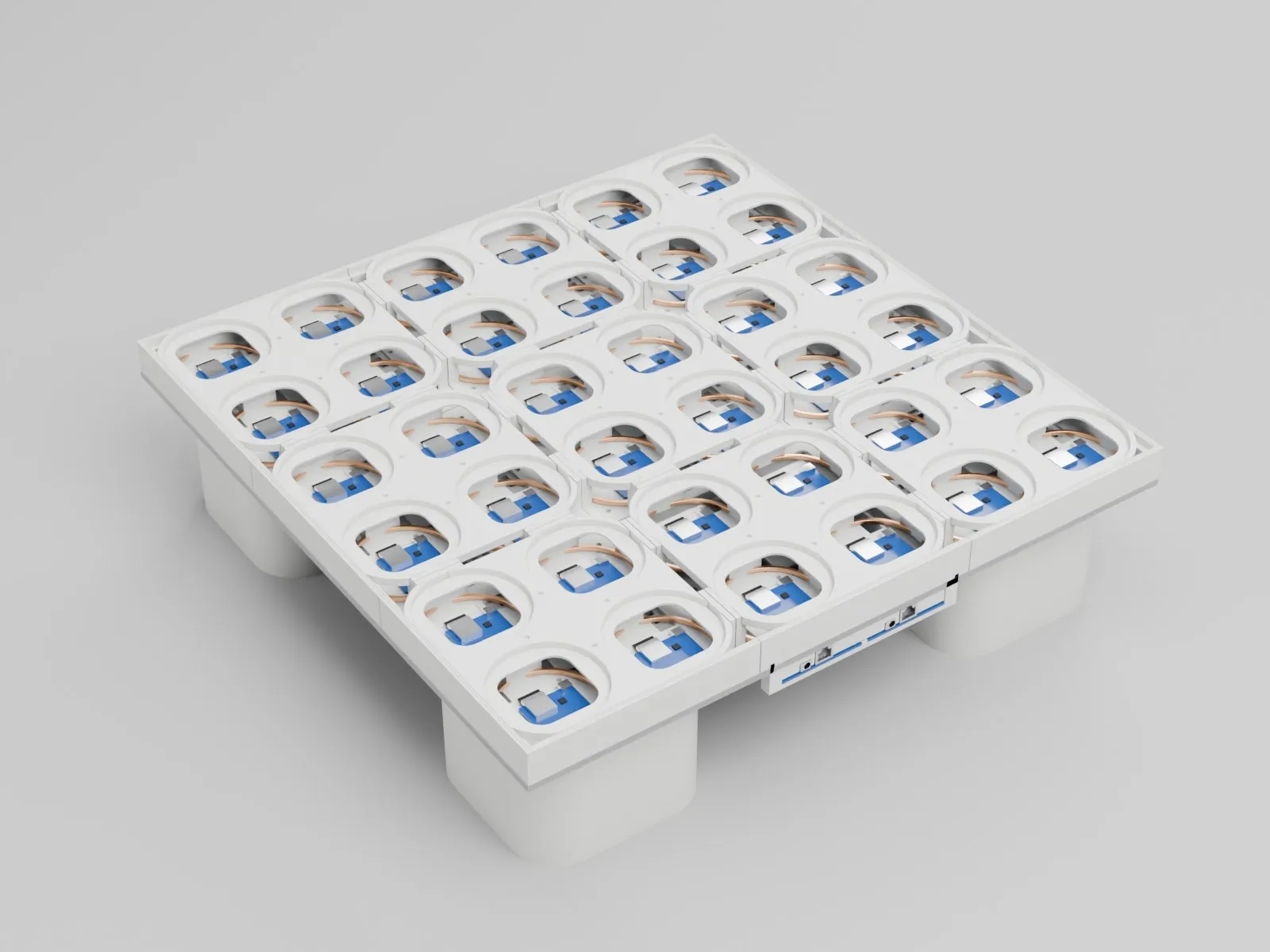
Figure: One block. Its network ports and DC power inputs are on the edge of the block
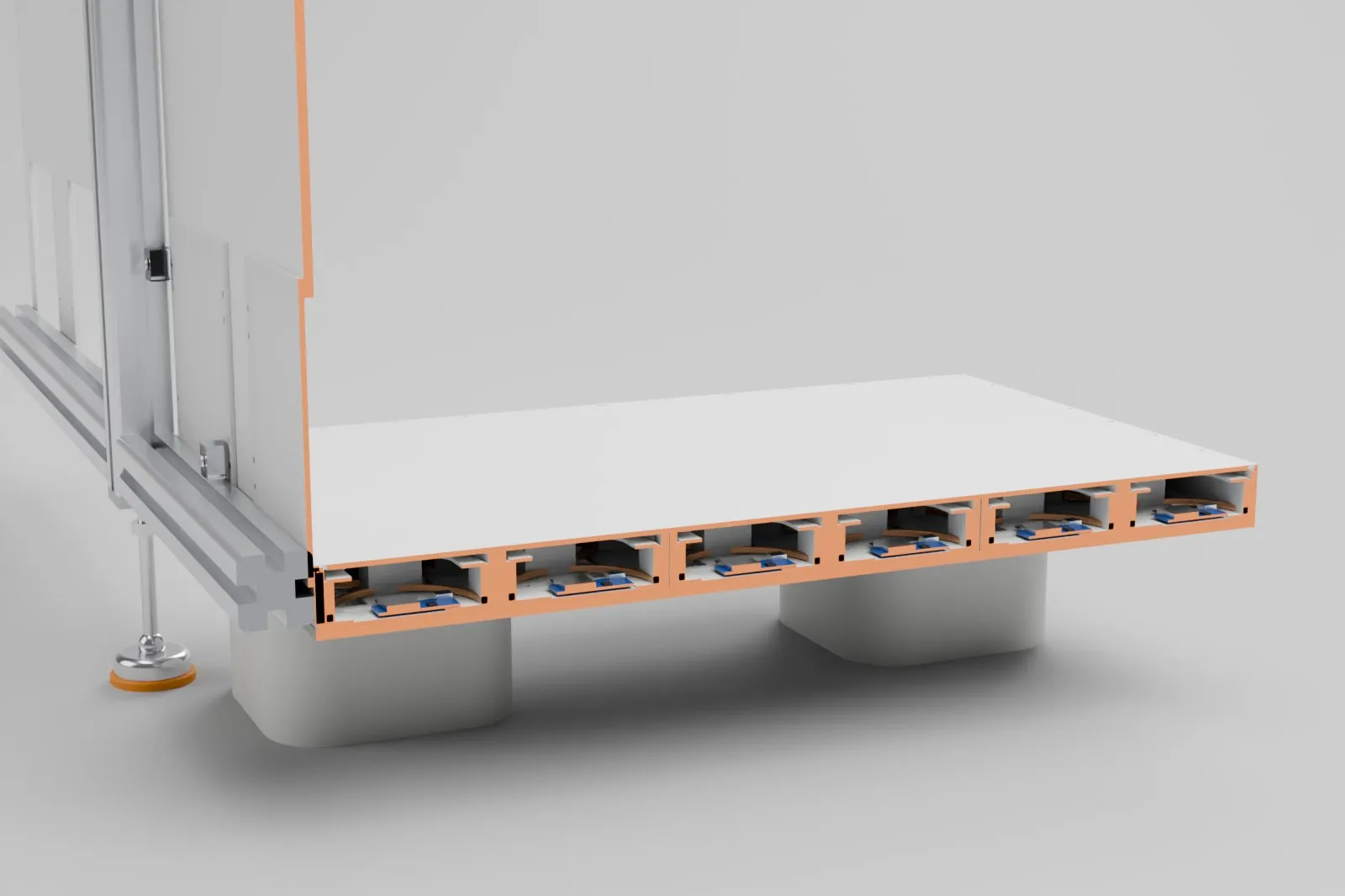
Figure: Section through the Reader Array, with the cut faces in orange. The coils and LF Reader Modules sit in trays; the floor platform is raised to leave a cooling air channel underneath
Imaging Subsystem
Section titled “Imaging Subsystem”The system has 1 Industrial Camera, monochrome with a global shutter, supporting 12 V or 24 V DC power and connected to the Compute Unit by USB 3.0. See Table “Camera specifications” for the specifications.
Table: Camera specifications
| Category | Parameter | Specification |
|---|---|---|
| Performance | Sensor type | CMOS, global shutter |
| Sensor model | Sony IMX264 | |
| Pixel size | 3.45 µm × 3.45 µm | |
| Sensor size | 2/3 in | |
| Resolution | 2448 × 2048 | |
| Max. frame rate | 60 fps @ 2448 × 2048 (Mono 8) | |
| Dynamic range | 71 dB | |
| SNR | 40 dB | |
| Gain | 0 dB to 24 dB | |
| Exposure time | Ultra-short exposure mode: 1 µs to 14 µs; standard exposure mode: 15 µs to 10 s | |
| Exposure mode | Off / Once / Continuous | |
| Color | Monochrome | |
| Pixel format | Mono 8/10/10Packed/12/12Packed | |
| Binning | Supports 1 × 1, 2 × 2, 4 × 4 | |
| Decimation | Supports 1 × 1, 2 × 2 | |
| Reverse image | Supports horizontal and vertical reverse image output | |
| Electrical | Data interface | USB 3.0 |
| Digital I/O | 6-pin P7 connector providing power and I/O: opto-isolated input × 1 (Line 0), opto-isolated output × 1 (Line 1), bi-directional non-isolated I/O × 1 (Line 2) | |
| Power supply | 9 VDC to 24 VDC; can also be powered over USB 3.0 | |
| Power consumption | Typ. 3.2 W @ 5 VDC (USB 3.0 power supply) | |
| Mechanical | Lens mount | C-mount |
| Dimensions | 29 mm × 29 mm × 30 mm | |
| Weight | Approx. 80 g | |
| Ingress protection | IP40 (with proper lens installation and wiring) |
Lighting Subsystem
Section titled “Lighting Subsystem”The lighting subsystem provides infrared illumination for video acquisition.
Table: Lighting subsystem specifications
| Parameter | Value |
|---|---|
| Lights | Infrared Light |
| Infrared wavelength | 940 nm |
| Infrared power per light | 25 W |
| Infrared supply input | 12 ~ 24 V DC |
| Number of Infrared Lights | 4 |
Environmental Sensor
Section titled “Environmental Sensor”The system has 1 environmental sensor, connected to the switch by network cable and supporting 12 V or 24 V DC power.
The measured environmental indicators and the specifications of each channel are given in Environmental Monitoring.
Compute Unit
Section titled “Compute Unit”Data processing is performed by the Compute Unit: External commercial computer connected via standard Ethernet. The Compute Unit is an independently powered, certified commercial product, used without modification.
Network Connections
Section titled “Network Connections”The Compute Unit, Reader Array and environmental sensor are all connected to the same switch by network cable and sit on the same local network. The Industrial Camera connects to the Compute Unit by USB 3.0 and is not on the network.
Each Reader Array block has 2 network ports. Keep all of them connected by network cable, 8 cables in total.
All devices connected through network ports must be on the same network segment and must use the router configured and supplied by Murinova, to avoid network problems. The network configuration is set up by Murinova before delivery; do not change it.
Use shielded network cable. Category 5e or higher is recommended. The parts of the system are not interconnected by wireless networking.